DIY Diode Fan Controller - The Diobus
- DIY Diode Fan Controller - The Diobus
- Part 1 - Some Info
- Part 2 - Indicator Lights:
- Part 3 - The Fan Controller Itself
- Part 4 - Some Soldering
- Part 5 - Final words
Part 2 - Indicator Lights:
Part 2 - Indicator Lights:
Lets start with some electronics.
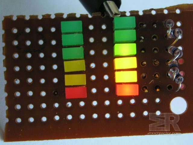
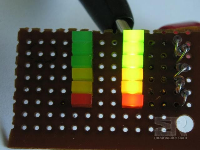
These are the two light bars which will indicate the viltage (speed) of the fans:
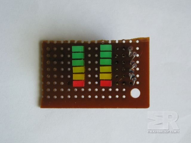
I used square LEDs, 0.06 BGN a piece, total 12 LEDs. I also used a piece of project board, 2-3 BGN the whole board.
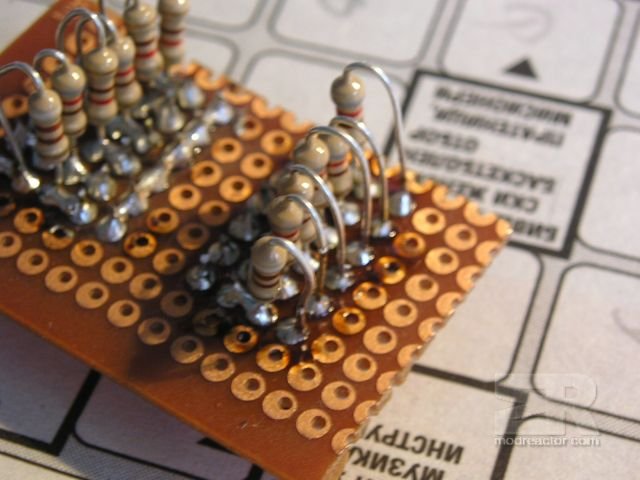
View from the back side. Resistors for the LEDs are displayed (LEDs are powered by 12V). 10 resistors - 0.06 BGN total. I used 12, but don;t remeber what exactly are their values.
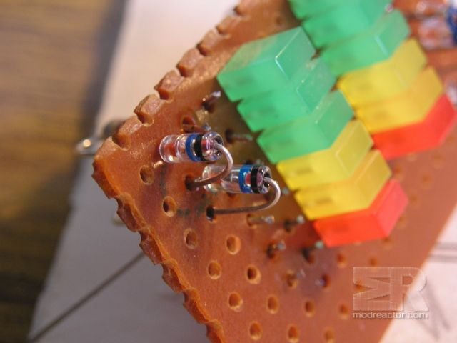
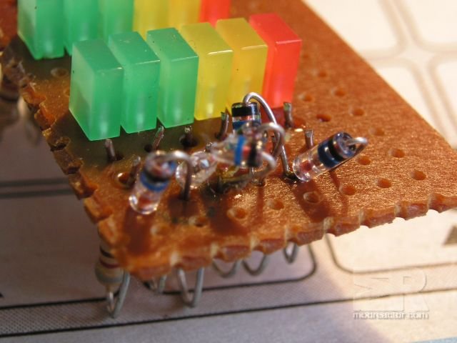
And these are some Schottky diodes, which force the current to flow only forward. Their purpose is to isolate the LEDs, which are above the current level of the indicator line. All of them were cheap, lets say about 1 BGN:
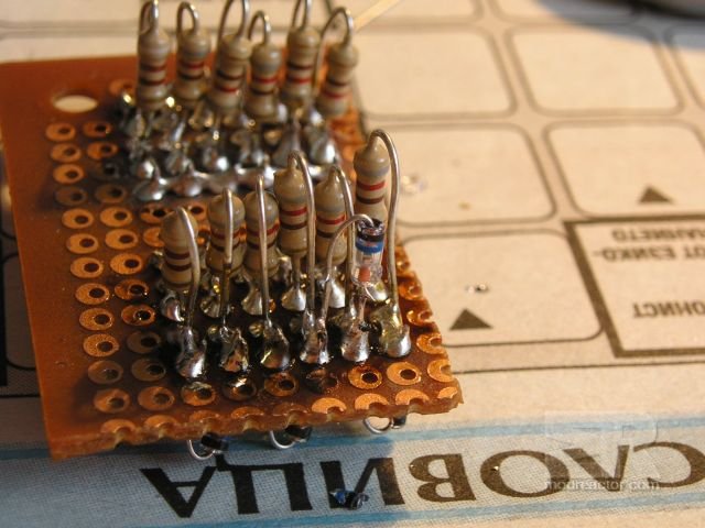
One of the diodes broke, they are very delicate, so I had to solder another from the backside (I always buy spare). During assenbly I broke another one, so now there are 2 of them on the back side: